- All
- Product Name
- Product Keyword
- Product Model
- Product Summary
- Product Description
- Multi Field Search

Smart Card / RFID Label / RFID Reader
Views: 0 Author: Site Editor Publish Time: 2022-03-15 Origin: Site


There are various types and categories of RFID labels, and choosing the right one is important to achieve the best possible application. The purpose of this article is to provide insight into the choices made when designing an RFID label and how these aspects affect the application.
This passage is going to talk about the followings of RFID labeling:
1) Components
2) How RFID label work?
3) How RFID label Designs?
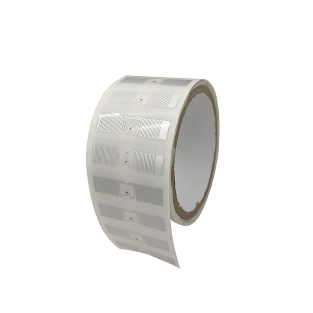
An RFID label has three different components: an RFID chip, consisting of an integrated circuit (IC), an antenna, and an underlay/base (called a substrate). These components are usually not made in-house by the tag manufacturer, but rather the workload is taken on by other manufacturers.
With passive RFID, when tags are not interacting with a reader, they are completely unpowered. Once the reader initiates the data exchange, it first drives the antenna, typically for 15 to 50 microseconds, to charge and power the tag's capacitors.
Data exchange is accomplished by a method called backscatter modulation. As the tag turns a load on and off, the reader's antenna undergoes a voltage change. This process is like a transformer: the reader is connected to the primary winding and the tag is connected to the secondary winding. Dropping a load on the secondary winding affects the primary winding.
Finally, RFID labels can be customized according to the intended use. These customizations are primarily in the housing, allowing the user to select an enclosure that best suits the environment and attachment method the tag will encounter. Other customizations include size, power options, and frequency.
We can customize your RFID label, reader, or any system. You can make a customization request here (URL).
A passive RFID label is divided into two main sections: the analog front-end and the digital section. The front-end tasks include all analog processing for DC power, incoming signal detection and information extraction (called demodulation) and the transmission of the modulation signal. The digital section decodes incoming data, responds to commands from the reader, reads and writes to internal EEPROM (electrically erasable programmable read-only memory) memory, and encodes and transmits data to the modulator. A backscatter modulator is a device used to modulate the impedance (the measure of the opposition that a circuit presents to a current when a voltage is applied) seen by the transponder’s antenna when transmitting, which decides the overall performance of the tag. The analog front-end is the key block of a passive RFID transponder. It provides a regulated voltage supply for the digital core and other circuits by correcting the incoming radio-frequency signal. While in transmitting mode, the analog front-end also works to ensure its communication method of backscatter modulation will function properly.
Passive RFID devices obtain their operating power from the radio-frequency waves transmitted from the RFID reader. This wireless link is classified into two groups based on the wireless link coupling mechanism: near-field coupling and far-field coupling. Near-field coupling is essentially an inductive coupling with frequencies up to a few MHz which forces the reader to be near, so the coupling coils of near-field coupled RFIDs will have a large voltage at their terminals and is not that severely affected by nearby devices. This is not the case for far-field coupling.
The efficiency in power harvesting is one of the key factors in determining the range of the tag. UHF RFID labels work on far-field coupling, thus their efficiency of power harvesting is an important factor in their design. This efficiency is determined by different factors such as the efficiency of the antenna, accuracy of the matching between the antenna and the circuitry, and the efficiency of the voltage multiplier.
In the case of near-field passive wireless systems, a diode bridge rectifier can be used to convert the carrier signal to DC.
Far-field RFID labels, on the other hand, require an efficient way to convert RF to DC. Voltage multipliers that increase voltage levels whilst performing the conversion are used, due to the low voltage of the antenna.
Antennas are a critical part of designing the reader, as they are required to efficiently carry a signal to and from the tag. PCB tracks are commonly used to form a loop. The range of a tag is affected by various factors, such as:
The tag’s antenna size. A larger antenna is better at being detected.
The reader’s antenna size. A larger antenna results in increased read range, but a noisy environment may cause a worse signal-to-noise ratio and decrease the reading distance
The orientation of the antenna
Environmental noise
The antenna’s Q factor. Generally, a Q between 30 and 40 is needed.
Most designs aim for an antenna between 0.8 and 1.6 µH, as values below 0.8 µH become increasingly more difficult to sync. Maximum energy transfer occurs when the antenna and associated components are in resonance.

